Analog Signals and Circuits
Analog Signals
An analog signal is a quantity that encodes information continuously in time. The word analog means that a quantity, for example an electrical voltage, is analogous to another physical quantity, for example the air pressure of sound waves.
Transducers are used to convert information from one form to another. For example, in music, microphones convert pressure waves into analog electrical signals, whereas speakers convert electrical signals into pressure waves.
Of course the reason for using analog electrical signals instead of pressure waves is that the former is much easier to manipulate than the latter. Electrical signals can be easily amplified, transported, mixed, filtered, recorded, etc, by specialized electrical circuits, some of which will be studied in the rest of this session.
Circuits with Resistors
Voltage and Current
Voltage is a measure of the (electric) potential energy across two points
Voltage is measured in Volts (V)
Current is a measure of the flow of (electric) charges (through a wire, device, surface, etc)
Current is measured in Amperes (A), Amps for short
Both voltage and current are signed quantities
We measure voltage across, v, and current through, i, a circuit element as indicated in the following diagram:
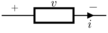
If both v and i have the same sign (both positive or both negative) then the element is dissipating energy (e.g. a toaster, a refrigerator, a computer)
If v and i have opposite signs then the element is generating energy (e.g. a battery, a power outlet)
A point in a circuit is called a node
Voltage Sources
You can buy voltage at the supermarket
You cannot buy current at the supermarket
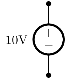
The symbol for a 10V voltage source is:
- Tasks
- Use a hand-help multimeter to measure the voltage across a 9V battery and the voltages on the breadboard pins
- Invert the polarity and explain your measurements
Ground node
If a circuit has a node from which all voltages are measured against this node is called the ground node or simply ground
Ground has its own special symbol:

Resistors
If two points that have different voltages are connect by an element that can carry electric charges then current will flow through the element connecting the two points (e.g. a wire, a circuit element, a toaster)
A resistor will limit the current that can flow through a circuit by offering resistance to the flow
Resistance is measured in Ohms (Ω)
A useful analogy is with the hydraulic circuit:
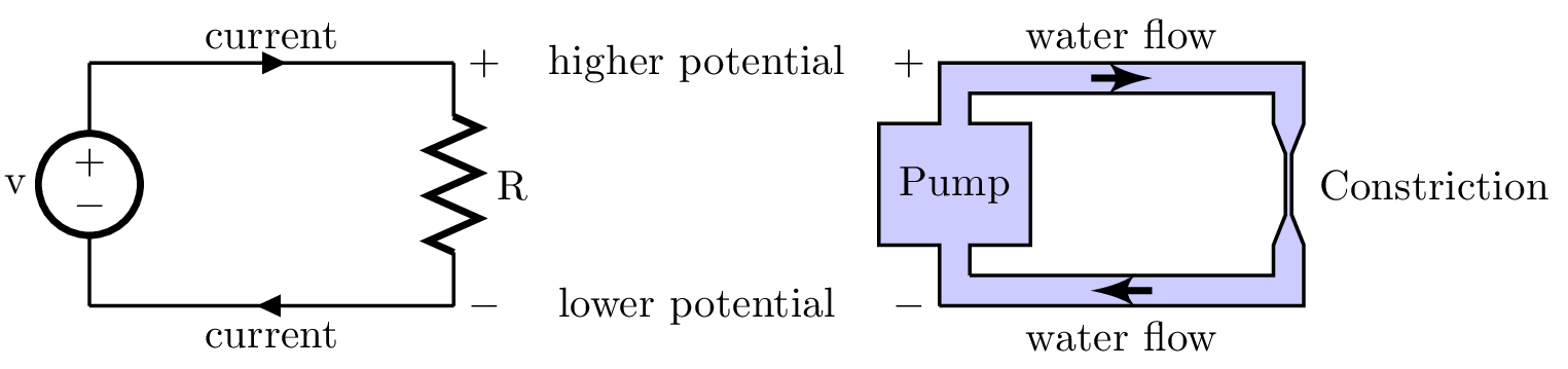
See this webpage for some great animations
The symbol for a 100KΩ resistor is:
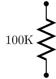
Since typing Greek is cumbersome we often omit the Omega symbol
Resistance values in resistor are encoded in color bars
The values of each color can be found in the table:
| Color | Value | Multiplier | Tolerance |
|---|---|---|---|
| Black | 0 | <math>\times 10^0</math> | <math>-</math> |
| Brown | 1 | <math>\times 10^1</math> | <math>\pm 1\%</math> |
| Red | 2 | <math>\times 10^2</math> | <math>\pm 2\%</math> |
| Orange | 3 | <math>\times 10^3</math> | <math>-</math> |
| Yellow | 4 | <math>\times 10^4</math> | <math>-</math> |
| Green | 5 | <math>\times 10^5</math> | <math>\pm 0.5\%</math> |
| Blue | 6 | <math>\times 10^6</math> | <math>\pm 0.25\%</math> |
| Violet | 7 | <math>\times 10^7</math> | <math>\pm 0.1\%</math> |
| Gray | 8 | <math>\times 10^8</math> | <math>\pm 0.05\%</math> |
| White | 9 | <math>\times 10^9</math> | <math>-</math> |
| Gold | <math>-</math> | <math>\times 10^{-1}</math> | <math>\pm 5\%</math> |
| Silver | <math>-</math> | <math>\times 10^{-2}</math> | <math>\pm 10\%</math> |
| None | <math>-</math> | <math>-</math> | <math>\pm 20\%</math> |
There are variations, but the most common is to have a resistor with four colored bars as in:
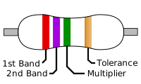
The above resistor has:
- 1st Band = Red = 2
- 2nd Band = Violet = 7
- Multiplier Band = Green = <math>\times 10^5</math>
- Tolerance Band = Gold = <math>\pm 5\%</math>
That is a 27 <math>\times 10^5</math>Ω resistor, i.e. 2.7MΩ resistor, with <math>\pm 5\%</math> tolerance
The <math>\pm 5\%</math> tolerance means that the resistance of the actual resistance might fall between 2.57M and 2.84M
If the fourth band is not present then the tolerance is <math>\pm 20\%</math>
Check out this link for more details
You can find many resistor calculators on the web, like this one from digikey
- Tasks
- Identity a 10K and a 100K resistors
- Use a hand-help multimeter to measure the resistance across a 10K and a 100K resistors
- Invert the polarity and measure again
Ohm's Law
A resistor imposes a linear relationship between voltage and current:
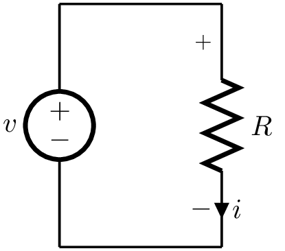
In the above circuit:
<math>v = R i \quad \text{or} \quad i = \frac{v}{R} </math>
- Tasks
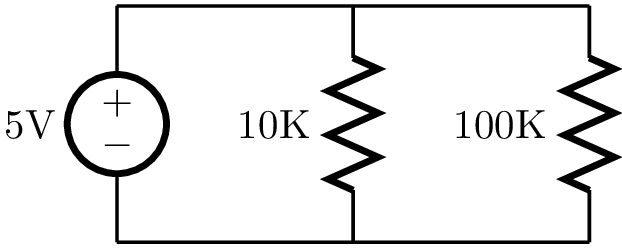
- Build this circuit on the breadboard:
- Use a hand-help multimeter to measure the voltage across and the current through the 10K and 100K resistors
- Measure the current through the voltage source
- What is the relationship between the currents?
- Tasks
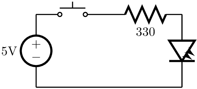
- Build this circuit on the breadboard:
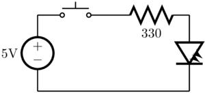
- The new elements are: a switch (push button) and an LED (Light Emitting Diode)
- Use a hand-help multimeter to measure the voltage across and the LED
- Use Ohm's Law to calculate the current on the circuit
- Flip the LED and see what happens
Association of Resistors
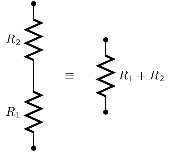
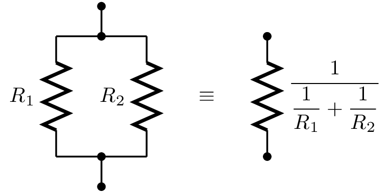
Resistors can be combined to produce different resistances
Series
In Parallel
- Tasks
- Measure the resistance of two 10K resistors in series and in parallel
- Measure the resistance of a 10K and a 100K resistors in series and in parallel
- Explain the value of the current through the voltage source you measured in the previous circuit
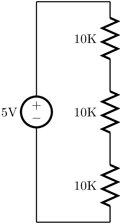
Voltage Division
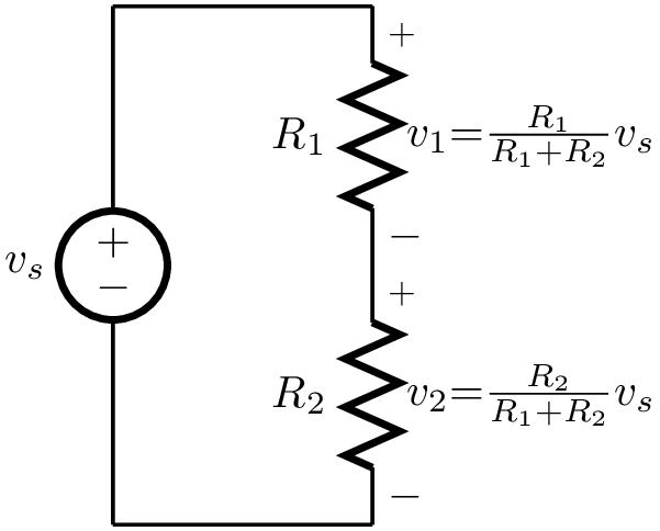
Follows from Ohm's law:
- Tasks
- Build this circuit on the breadboard:
- Use a hand-help multimeter to measure the voltage across and the current through the resistors and the voltage source
- Explain the value of the current using association of resistors
- What is the relationship between the voltages?
Potentiometers
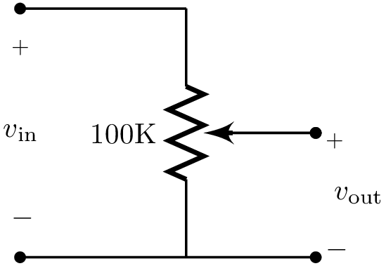
A potentiometer is a variable voltage divider
The symbol for a 10K potentiometer is:
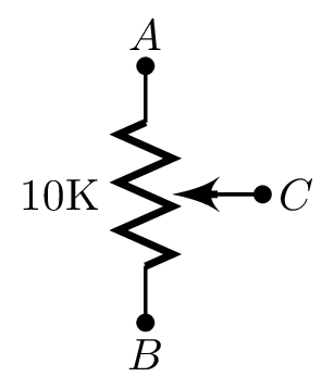
If you leave <math>C</math> unconnected the potentiometer is a constant resistor
If you leave <math>A</math> or <math>B</math> unconnected the potentiometer is a variable resistor
The relationship between the resistances in the above potentiometer is:
<math> R_{AB} = R_{AC} + R_{CB} = 10\mathrm{K}\Omega</math>
- Tasks
- Use a hand-help multimeter to measure the resistance between the terminals of a 10K potentiometer while you move the wiper
- Which terminal is <math>C</math>?
- Explain how the following circuit can be used as a volume control circuit:
- Connect the output of a LB oscillator to a potentiometer working as a volume control
- Inspect the output using the oscilloscope as you move the wiper
- Connect the output to a LB speaker
- Advanced Tasks
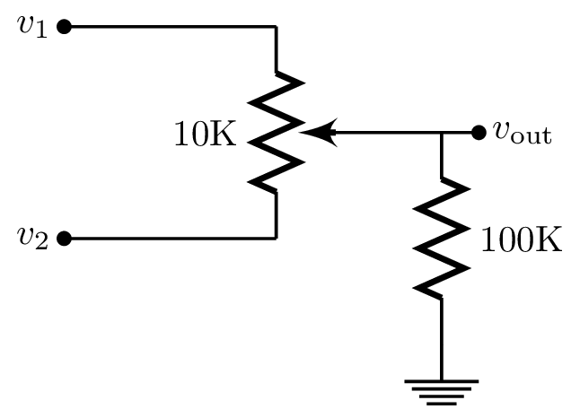
- Build the following cross-fader circuit on the breadboard:
- Borrow a cable from another group and connect two different LB oscillators to the inputs <math>v_1</math> and <math>v_2</math>
- Inspect the output using the oscilloscope as you move the wiper
- Connect the output to a LB speaker
Circuits with Capacitors
Capacitors
Capacitors are devices that can store electric charge
Capacitance is measured in Farads (F)
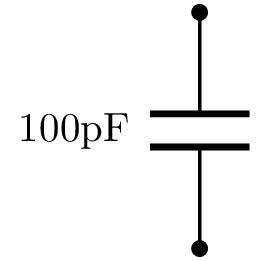
The symbol for a 100pF capacitor is:
Capacitors may also be color coded but more commonly they value is printed on the capacitor.
Most ceramic and other popular types of capacitors come marked with three numbers, which are read as done with resistors: value value multiplier
The units in this case however are pF (pico Farads)
For example, a capacitor marked 472 is a 47 <math>\times 10^2</math>pF capacitor, or a 4700pF = 4.7μF capacitor
There are variations though, so be careful. See this page for other marking methods
Some types of capacitors are polarized, most notably electrolytic capacitors
BE CAREFUL: a polarized capacitor is often destroyed if connected inverted!
- Tasks
- Add a capacitor to the LED circuit:
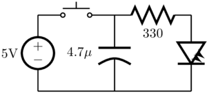
- ATTENTION: The type of capacitor you will have to use here is polarized and can only be connected as shown!
- Replace the capacitor by a 470μF capacitor
- What happens if you momentarily close the switch periodically for a short period of time?
- Try keeping the time the switch is closed constant and varying the period
Filters
Circuits with capacitors can be used to filter signals
High-Pass Filter
The following circuit is essentially a voltage divider:
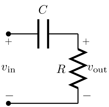
However, it is not obvious how to calculate the output voltage as a function of the input voltage
The main difficulty is that the response will now depend on the input voltage
Even when the input voltage is constant, the output voltage may still vary: the circuit has become dynamic
It is relatively easy to characterize the response to simple sinusoidal inputs
If the input voltage is
<math>v_\mathrm{in} = A \cos(2 \pi f \, t) </math>
then, after the circuit has been operating for some time (we say in steady-state), the output voltage will become closer and closer to
<math>v_\mathrm{out} = A G \cos(2 \pi f\, t + \phi)</math>
In other words, the steady-state output will also be a sinusoidal function of same frequency but with a different amplitude and phase
The exact steady state amplitude and phase depends on the circuit
For the above circuit the frequency-dependent gain <math>G</math> is equal to
<math> G = \frac{|f/f_c|}{\sqrt{1 + (f/f_c)^2}}, \qquad f_c = \frac{1}{2 \pi R C} </math>
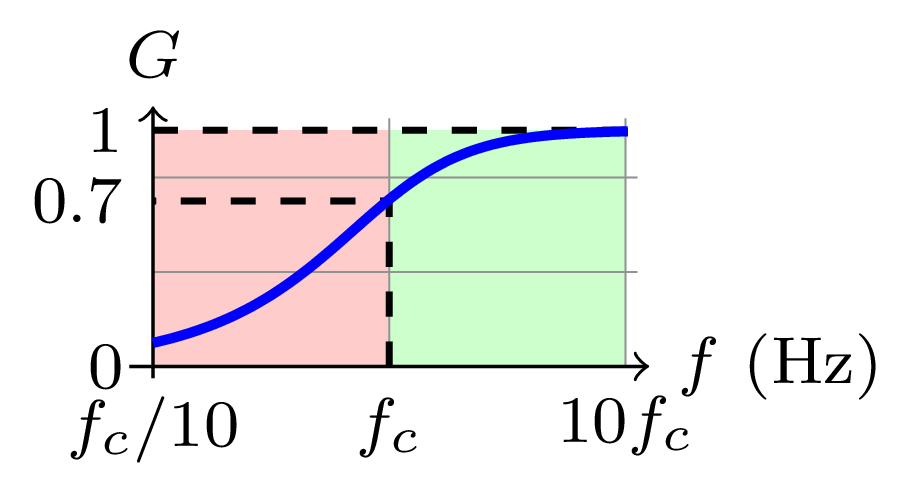
The value of the gain <math>G</math> can be plotted (in logarithmic scale) as a function of the input voltage frequency <math>f</math>:
A summary of the behaviour is as follows:
- When <math>f</math> is small then <math>G</math> is small.
- When <math>f \approx f_c</math> then <math>G</math> is close to 0.7.
- When <math>f</math> is large then <math>G</math> is close to 1.
The circuit is a high-pass filter, because high frequencies are allowed to pass (<math>G \rightarrow 1</math>) while low frequencies are attenuated (<math>G \rightarrow 0</math>)
The frequency <math>f_c</math> is known as the filter's cutoff frequency, as it roughly marks the boundary between the region where frequencies are attenuated from the region where frequencies are allowed to pass
- Tasks
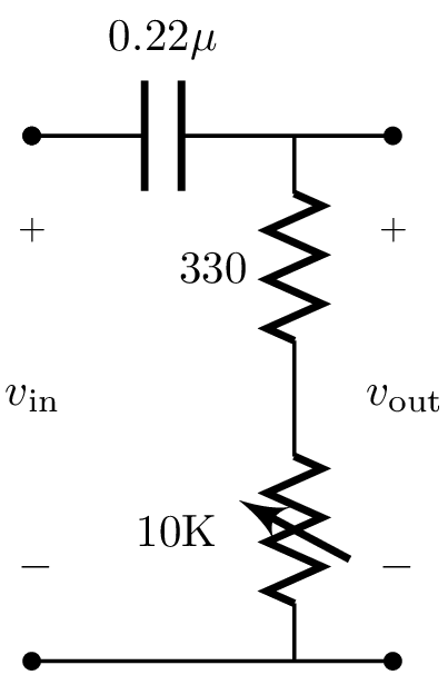
- Build the high-pass filter on the breadboard:
- Calculate the cutoff frequency as a function of the variable resistor
- Connect the input to a LB oscillator
- Inspect the output using the oscilloscope as you move the wiper
- Vary the frequency of the oscillator and your circuit potentiometer wiper
- Tasks
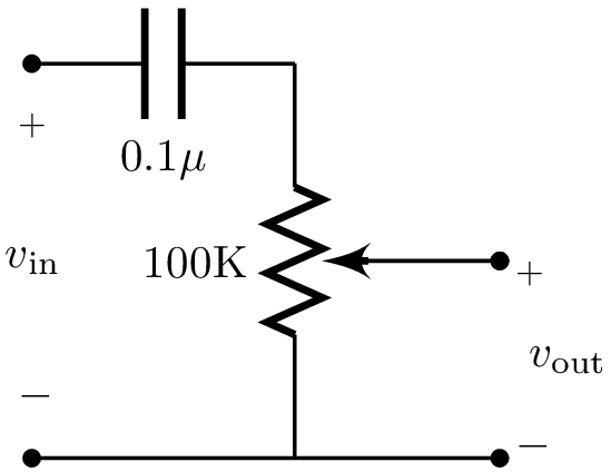
- Insert a capacitor in series with a potentiometer as in:
- Calculate the cutoff frequency for this hi-pass filter
- Connect the input to a LB oscillator
- Inspect the output using the oscilloscope as you move the wiper
- Tasks
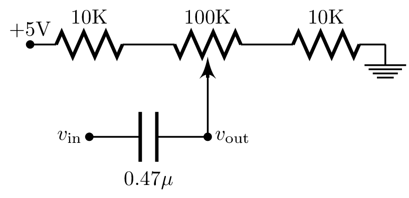
- Insert a capacitor in series with a potentiometer as in:
- Calculate the minimum cutoff frequency for this hi-pass filter
- Connect the input to a LB oscillator
- Inspect the output using the oscilloscope as you move the wiper
Low-Pass Filter
If we invert the position of the resistor and capacitor:
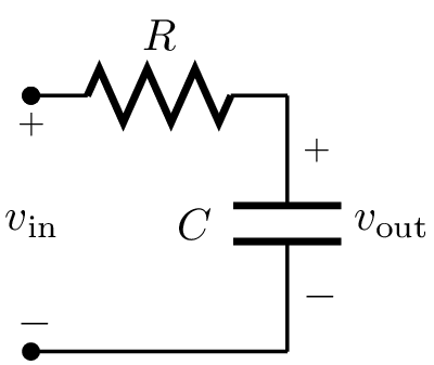
the resulting circuit has a frequency-dependent gain <math>G</math>:
<math> G = \frac{1}{\sqrt{1 + (f/f_c)^2}}, \qquad f_c = \frac{1}{2 \pi R C} </math>
The value of the gain <math>G</math> can be plotted (in logarithmic scale) as a function of the input voltage frequency <math>f</math>:
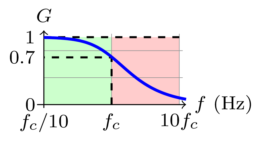
A summary of the behaviour is as follows:
- When <math>f</math> is small then <math>G</math> is close to 1.
- When <math>f \approx f_c</math> then <math>G</math> is close to 0.7.
- When <math>f</math> is large then <math>G</math> is small.
The circuit is a low-pass filter, because low frequencies are allowed to pass (<math>G \rightarrow 1</math>) while high frequencies are attenuated (<math>G \rightarrow 0</math>)
The frequency <math>f_c</math> is known as the filter's cutoff frequency, as it roughly marks the boundary between the region where frequencies are attenuated from the region where frequencies are allowed to pass
- Tasks
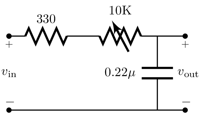
- Build the low-pass filter on the breadboard:
- Calculate the cutoff frequency as a function of the variable resistor
- Connect the input to a LB oscillator
- Inspect the output using the oscilloscope as you move the wiper
- Vary the frequency of the oscillator and your circuit potentiometer wiper
Circuits with OpAmps
OpAmps
An OpAmp is an easy to use diferential amplifier with a very high gain
The symbol for an OpAmp is:

- The inputs labelled <math>v_\mathrm{dd}</math> and <math>v_\mathrm{ss}</math> are connected to constant supply voltages, with LB <math>v_\mathrm{dd} = 5\mathrm{V}</math> and <math>v_\mathrm{ss}</math> is ground
- IMPORTANT: The supply voltages are usually omitted in diagrams but have to be connected for the circuit to work!
- The inputs labelled <math>v_{+}</math> and <math>v_{-}</math> are connected to signal voltages
- The output labelled <math>v_\mathrm{out}</math> is the signal output
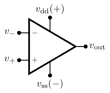
Mathematically:
<math>v_o = K (v_+ - v_-)</math>
where the gain K is very large
OpAmps have very high input impedances (think resistance) and very low output impedance
We will use the OpAmp MCP6271
MCP6271
Each IC contains one OpAmp and the pins correspond to:
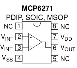
Use the notch on top of the package to locate the pins
Pins marked with NC need not be connected
Some of its characteristics are:
- Gain (K): 3.2 x 10⁵
- Input impedance: 10GΩ
- Bandwidth: 2MHz
- Slew-rate: 0.9V/μs
Basic Amplifier Circuits with OpAmps
When operated in feedback:
<math>v_+ \approx v_-</math>
That's all you need to know to start playing with OpAmps!
Here are some useful circuits:
Non-Inverting OpAmp Circuit
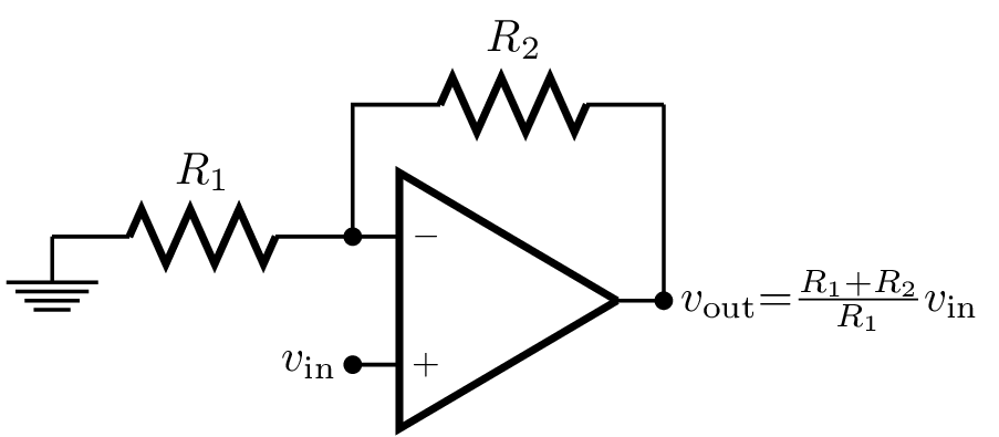
Works like a voltage divider:
<math> \begin{align} v_- &= \frac{R_1}{R_1+R_2} v_\mathrm{out}, & &\qquad & v_+ = v_- &= v_\mathrm{in} \end{align} </math>
A special case of the Non-Inverting OpAmp circuit is when <math>R_1</math> is <math>\infty</math>, which is the following very useful circuit:
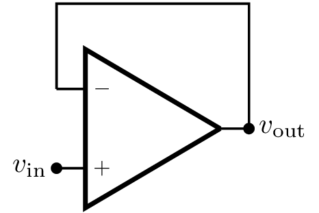
- Tasks
- Assemble the above circuit on the breadboard and connect the output of a LB oscillator to its input
- Look at the input and output signals using the oscilloscope
- Can you tell why this circuit is called a buffer?
Because the OpAmp has very high input impedance the following circuit works as an impedance matcher:
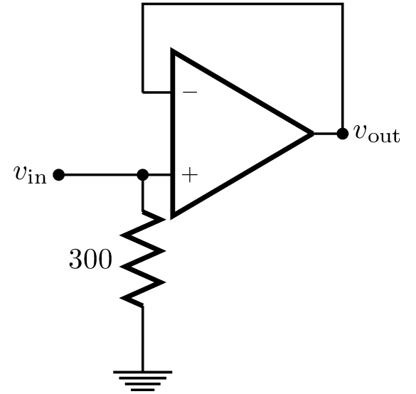
The input sees as load the 300Ω resistance rather than the high impedance of the amplifier or the impedance of the circuit the amplifier is connected to
We will demonstrate the virtues of impedance matching using contact microphones
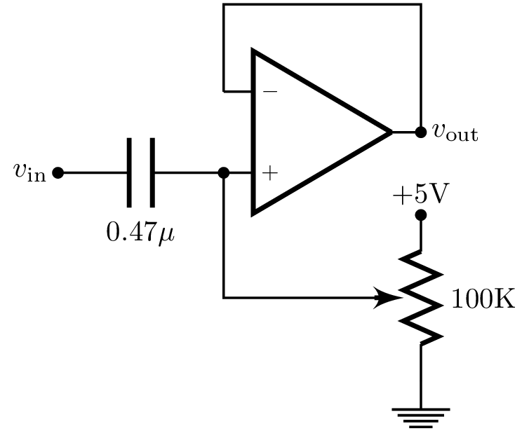
Now let's combine a buffer with a voltage divider:
- Tasks
- Assemble the above circuit on the breadboard and connect the output of a LB oscillator to its input
- Look at the input and output signals using the oscilloscope
- How is this circuit different than a buffer?
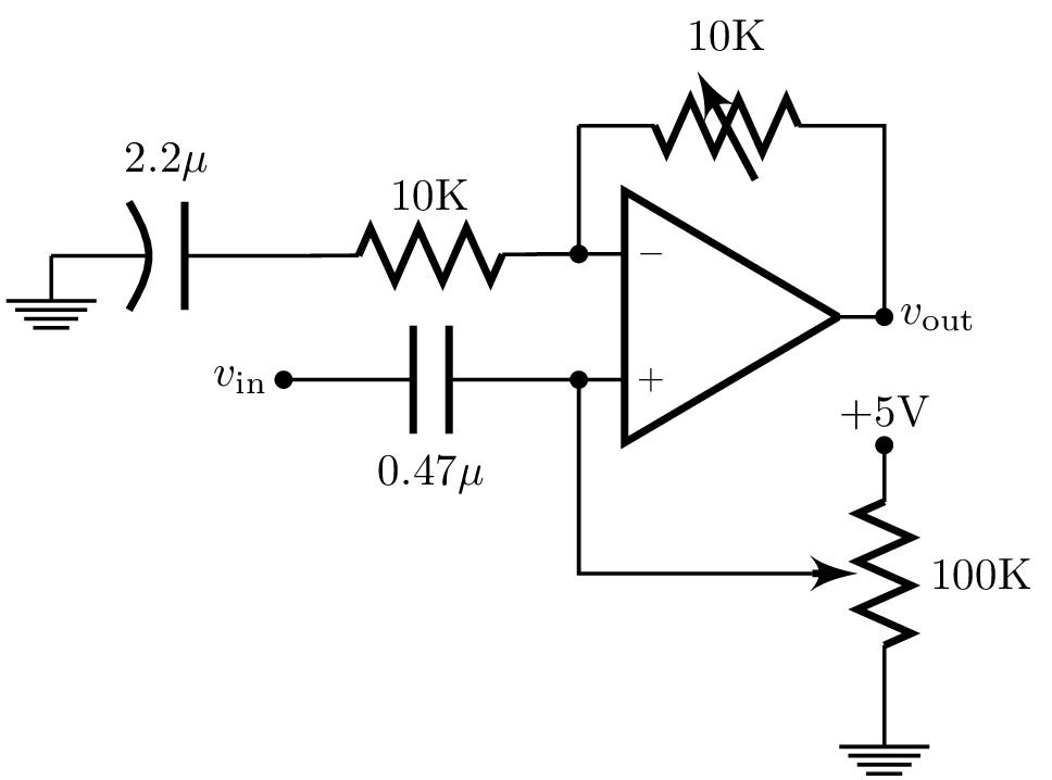
Our last circuit is a practical AC Non-Inverting OpAmp:
- Tasks
- Assemble the above circuit on the breadboard and connect the output of a LB oscillator to its input
- Look at the input and output signals using the oscilloscope
- Explain what this circuit does.
Inverting OpAmp Circuit
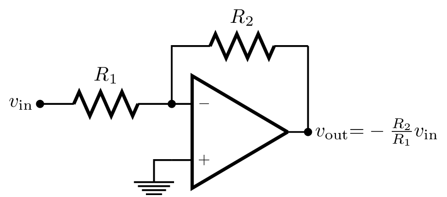
Another voltage divider:
<math> \begin{align} (v_- - v_\mathrm{in}) &= \frac{R_1}{R_1+R_2} (v_\mathrm{out} - v_\mathrm{in}), & & \qquad & v_+ = v_- &= 0 \end{align} </math>
An Inverting OpAmp Circuit can be modified to work as a mixer:
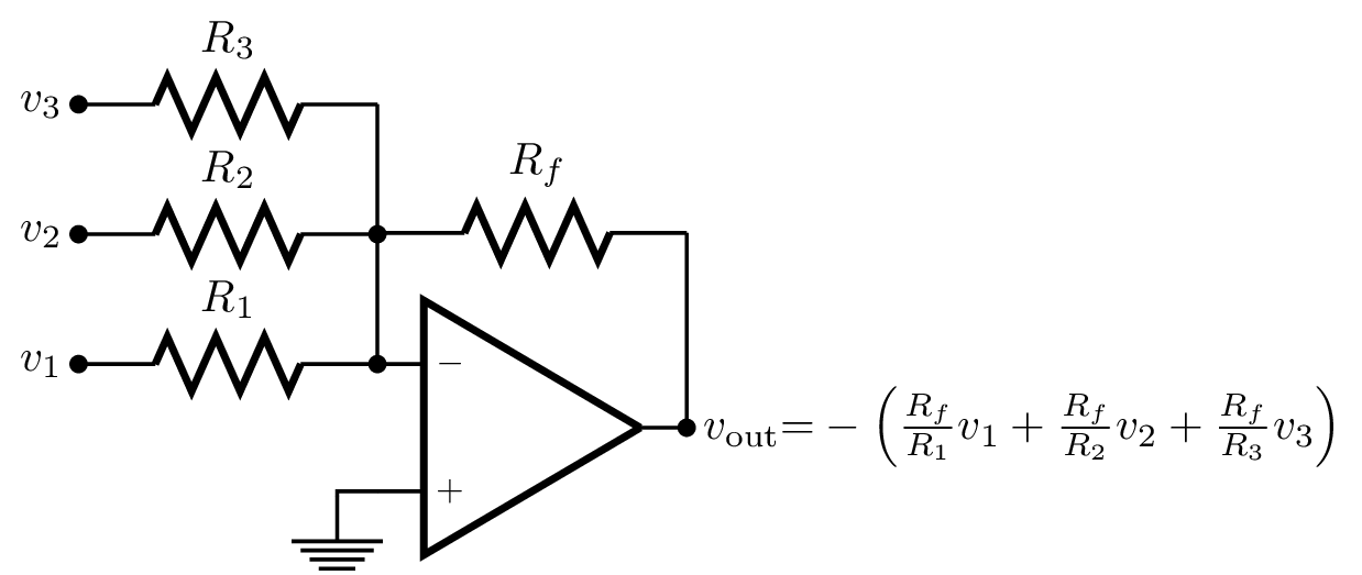
The following is a practical AC-coupled mixer circuit:
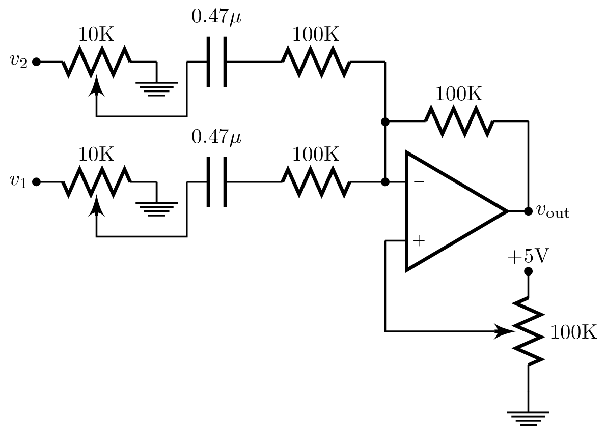
- Tasks
- Assemble the above circuit on the breadboard
- Team up with another group and connect the output of two LB oscillators to its 2 inputs
- Look at the input and output signals using the oscilloscope
- Explain how the circuit works
- Why did we not make the 100K resistors variable?
Non-Linear Circuits
- Saturation and Distortion
- Diodes
- Clipper
- Compressor